Caster modules
Estimated time: 4 hours
This page will guide you through assembly of the four caster modules.
Swerve module assembly
Estimated time: 1 hour
Tools:
- Imperial hex keys (3/16", 5/32", and 1/8")
Our caster module is adapted from the SDS MK4 swerve module, widely used in the FIRST robotics competition (FRC). The adaptation involved minor modifications to the bottom portion of the module.
| Caster module | Swerve module |
|---|---|
 |
 |
Note
The modifications add a caster offset to the wheel, similar to the offset found in office chair wheels. Our paper explains in more detail why this offset is important.
| Caster module | Swerve module |
|---|---|
 |
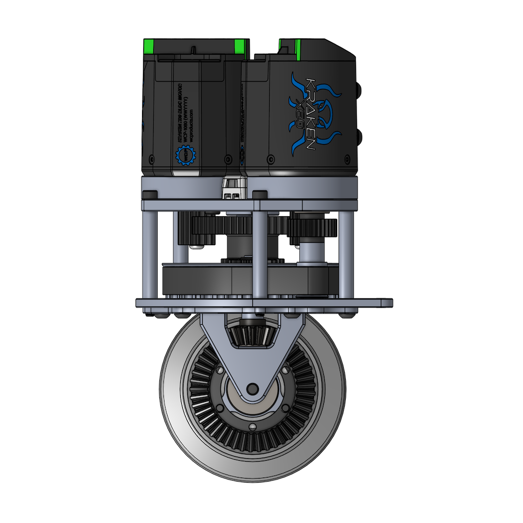 |
In our caster module, aside from three custom parts, all other components are reused directly from the swerve module kit, so the assembly process is very similar. Therefore, we highly recommend performing a practice assembly of an unmodified swerve module first to familiarize yourself with the process and all the different parts:
After you have completed the practice assembly, please disassemble the swerve module before proceeding.
Note
There is no need to use threadlocker or carefully tighten screws during the practice assembly, as the swerve module will be disassembled afterward. You can also skip any steps involving the encoder and encoder magnet for now.
Note
Use the following configurations when assembling the swerve module:
- Motor: Kraken X60 with risers
- Wheel: Colson wheel (secured with 3 screws instead of 6)
- Intermediate shaft: V3
Note
The swerve module kit uses hex screws in Imperial sizes only. To avoid accidentally stripping screws, do not use any metric hex keys during assembly. If you are using Bondhus hex tools, use only the yellow ones, not the red ones.
Note
After assembly is complete, the only leftover parts should be four extra screws. They are not used because the Kraken motor risers require slightly longer screws.
Tip
All screws should go in smoothly and not feel tight until they are fully inserted. If a screw encounters resistance when it is only partially inserted, it is likely due to misalignment. Loosen the screw, realign it, and try again.
Tip
We highly recommend working in an uncluttered space and keeping parts in their original bags. Parts can easily be dropped during assembly, causing small screws to scatter everywhere.
Tip
Please pay special attention to small parts such as the E-clip, shim, encoder magnet, and encoder housing screws, as they can easily get lost.
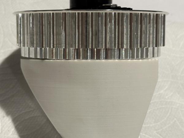
Wheel mount printing
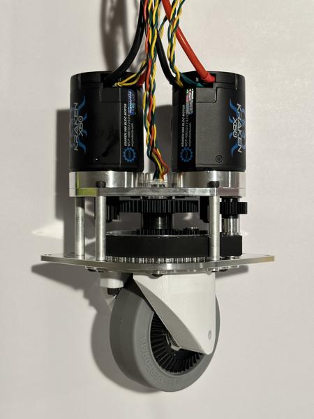
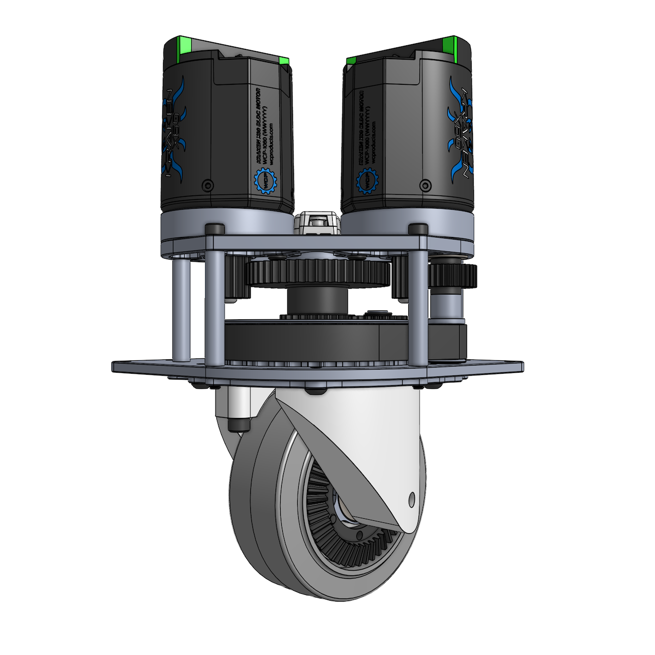
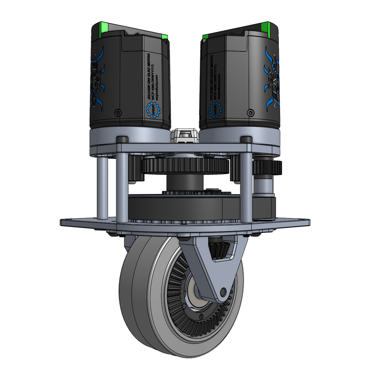
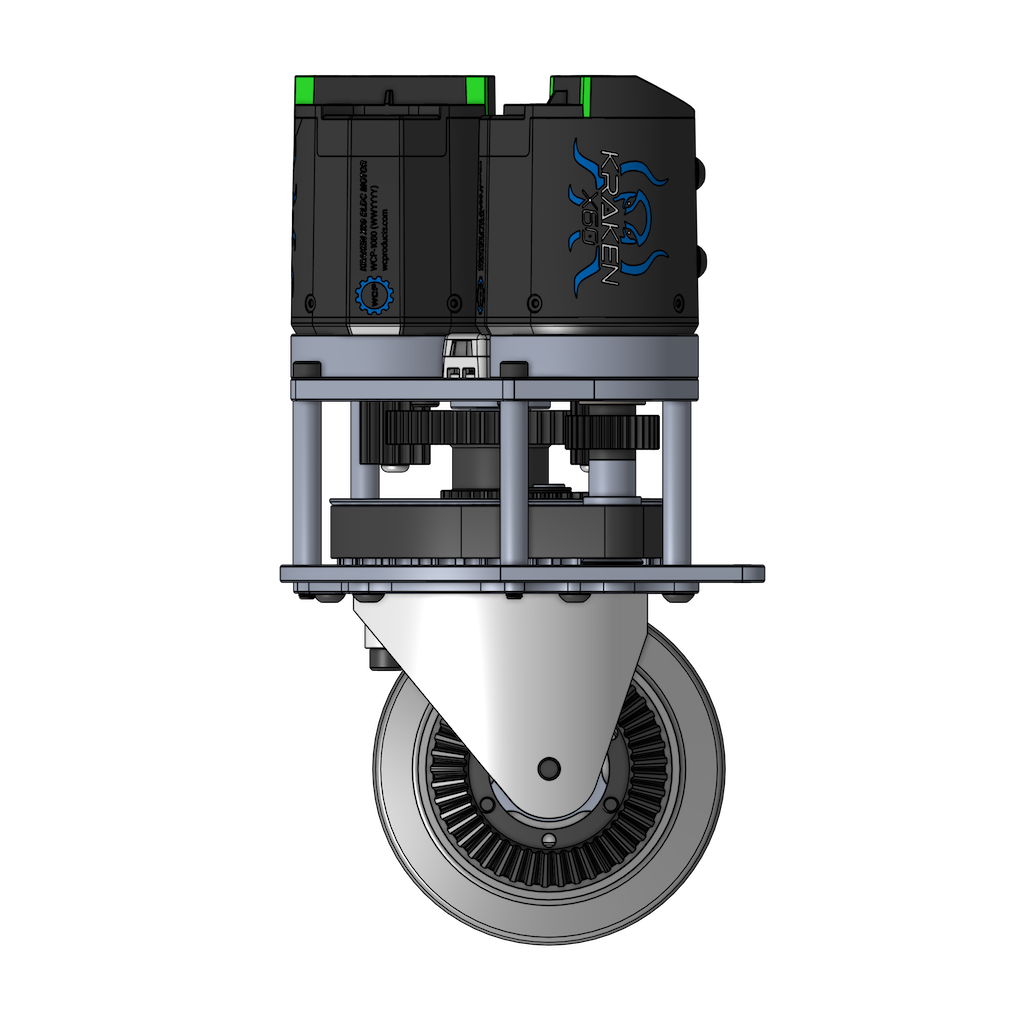
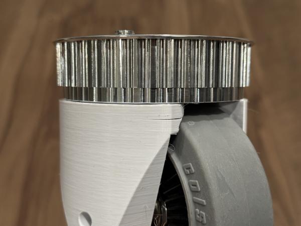
Each caster module uses a pair of custom 3D-printed wheel mounts. Below are a few photos showing the wheel mounts installed on the caster module:
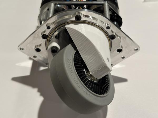
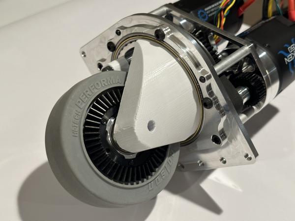
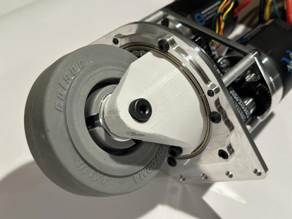
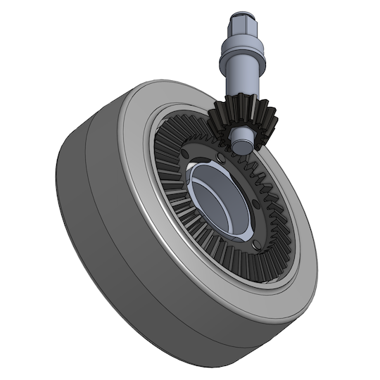
The wheel mounts hold the two bevel gears in precise alignment, as shown below, so high print accuracy is required. If the gears are too close together, gear interference will occur, preventing the wheel from turning smoothly.
We have made successful prints on several 3D printers. Below, we provide the print files we used. If your printer is listed, we recommend using the provided 3MF or G-code files. For other printers, we provide the STL files along with minimal slicer settings.
Print files
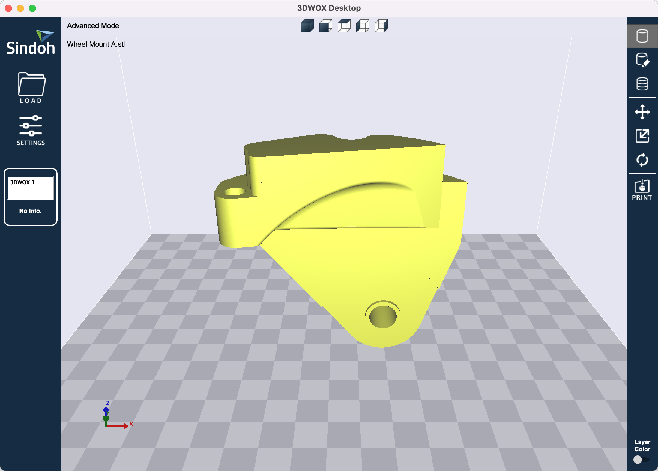
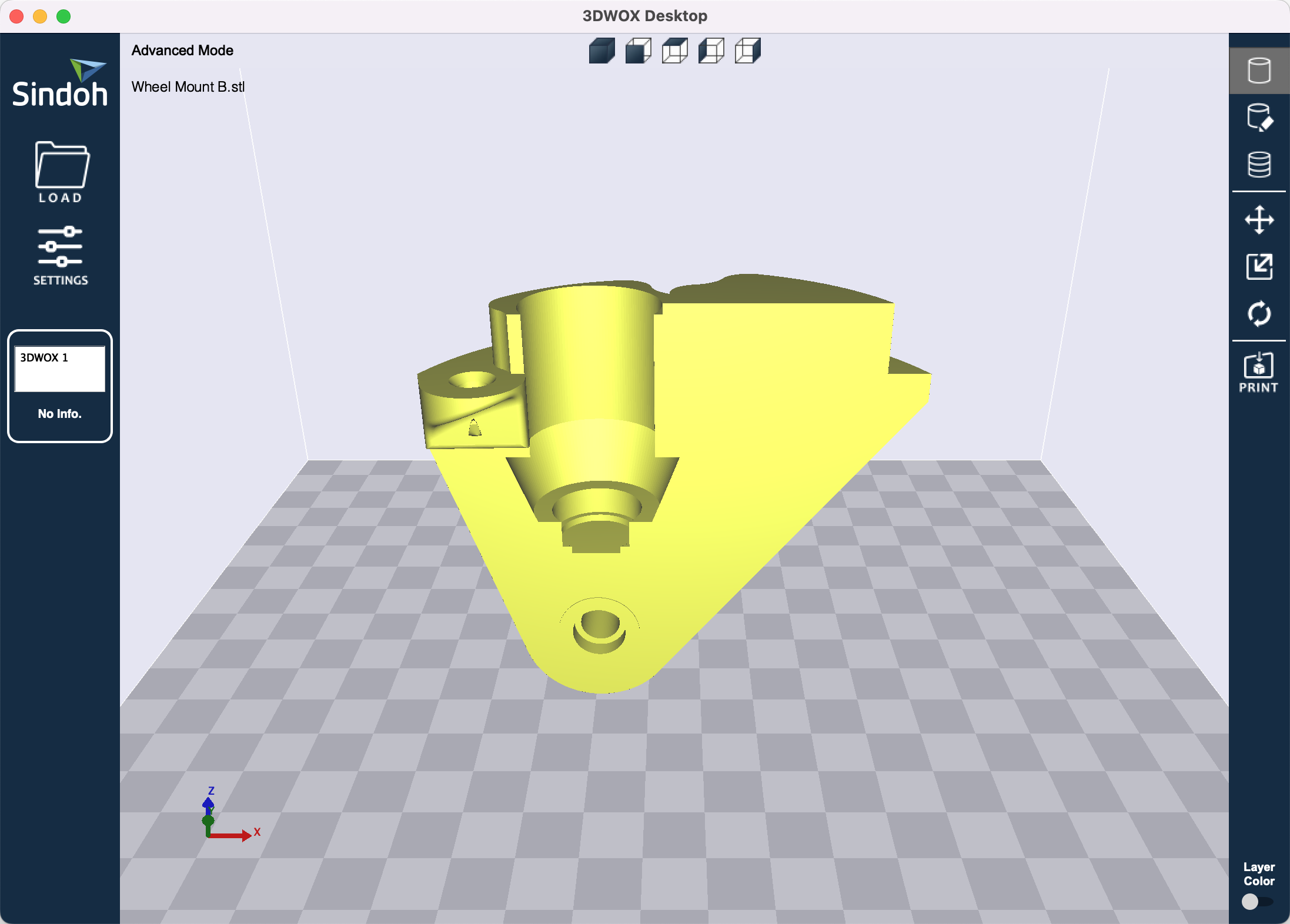
Sindoh 3DWOX 1
Slicer settings
3DWOX Desktop
- Both wheel mounts:
- Settings > Support > Overhang Angle (deg): 30 (default is 60)
- Wheel mount B only:
- Settings > Quality / Shell > Shell > Wall Thickness (mm): 1.6 (default is 0.8)
Bambu Lab X1-Carbon
Bambu Lab X1E
Slicer settings
Bambu Studio
- Both wheel mounts:
- Filament: Bambu PLA Basic
- Process: 0.20mm Standard @BBL X1C
- Support > Enable support: true (default is false)
- Supports Painting > Tool type: Fill (default is Circle)
- Apply to all overhang regions
- Wheel mount B only:
- Strength > Wall loops: 4 (default is 2)
Original Prusa MK3.9
Original Prusa MK3.5
Slicer settings
PrusaSlicer
- Both wheel mounts:
- Filament: Generic PLA
- Print Settings > Support material > Generate support material: true (default is false)
- Paint-on supports > Tool type: Smart fill (default is Brush)
- Apply to all overhang regions
- Wheel mount B only:
- Layers and perimeters > Vertical shells > Perimeters: 4 (default is 2)
STL files
Minimal slicer settings
- Both wheel mounts:
- Enable supports
- Apply paint-on supports to all overhang regions
- Wheel mount B only:
- Increase wall/shell loops from 2 to 4 (0.8 mm to 1.6 mm)
Note
Please perform bed leveling to improve print accuracy. On higher-end printers, this process is often done automatically.
Note
We tested these printers and do not recommend using them due to their low print quality:
- Creality Ender-3
- Creality Ender-3 S1 Pro
- Creality Ender-5 S1
Original STEP files
If you wish to make your own modifications to the CAD design, the original STEP files are available here:
| Wheel mount A | Wheel mount B |
|---|---|
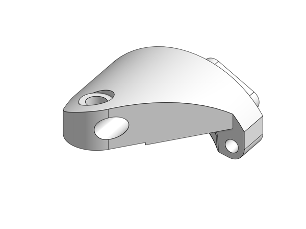 [STEP] |
 [STEP] |
For 3D printing, we made the following modifications to account for printer tolerances, then exported to STL format:
- Both wheel mounts:
- Reduce the width of the top protrusion that fits into the base pulley by 0.004" radially
- Increase the width of the clearance portion of the shoulder screw hole by 0.004" radially
- Wheel mount B only:
- Apply a 0.05" chamfer to the edge of the two mounting holes to account for burr formation during screw self-tapping
- Increase the width of the threaded portion of the shoulder screw hole by 0.015" radially (from 0.257" to 0.287")
- Increase the width of the bearing housing by 0.004" radially
- Add an integrated shim around the edge of the shoulder screw hole with a thickness of 0.008"
Note that the integrated shim (highlighted in orange below) helps ensure proper bevel gear spacing:
![]()
Note
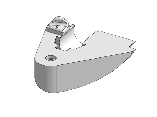
The top portions of the wheel mounts need to be printed accurately to ensure proper contact with the base pulley. Therefore, the wheel mounts should be printed in the upright orientation as shown below. Do not print them upside down.
Note
All overhang regions must be fully supported during printing:
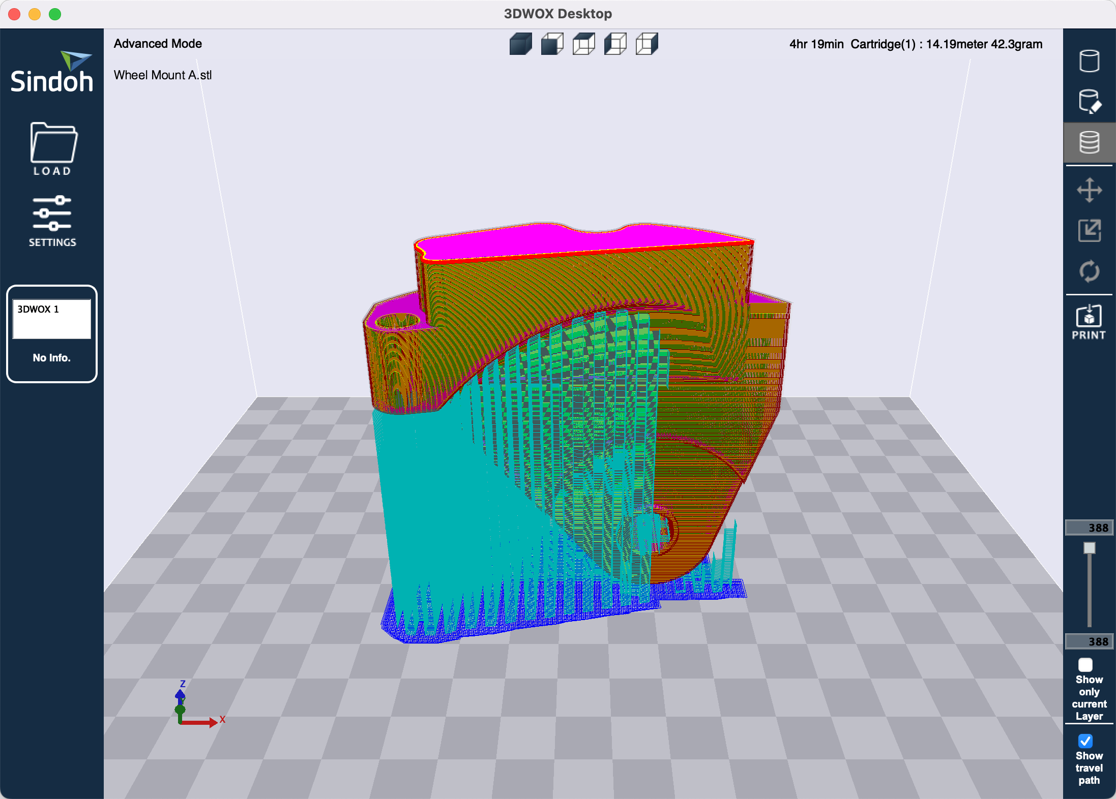
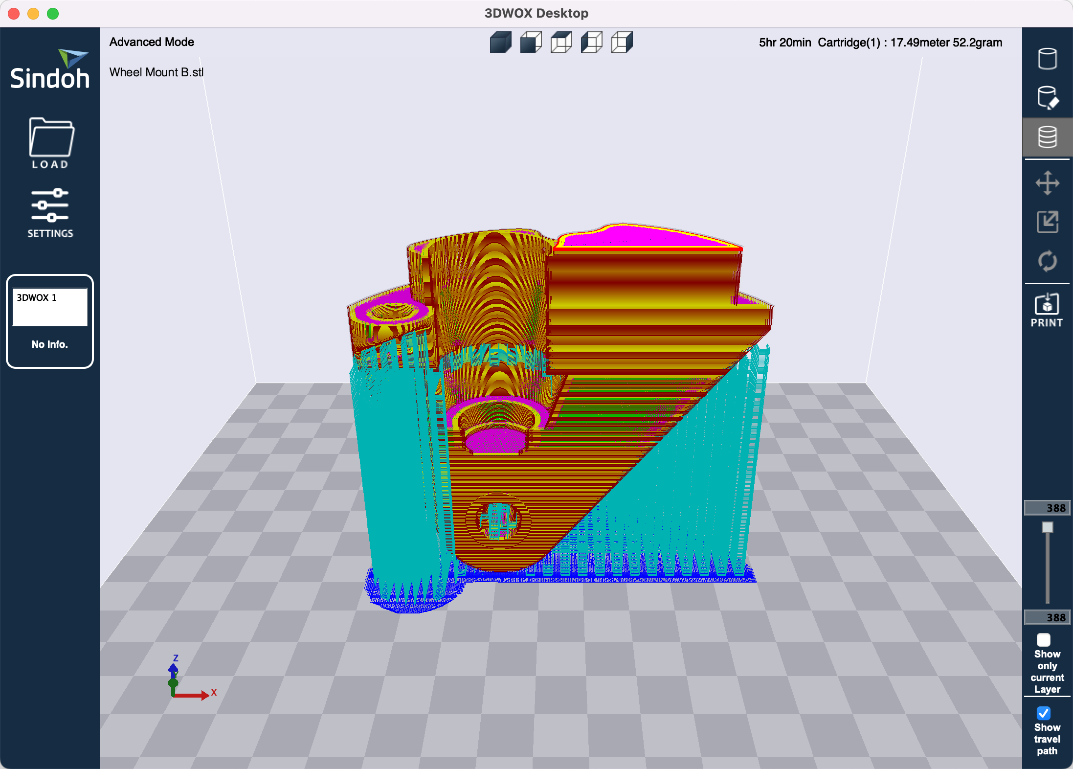
In many slicers, the auto-generated supports may be incomplete, so you may need to add paint-on supports manually. For example, this video shows how to do this in Bambu Studio:
Tip
We recommend printing a few extra copies of wheel mount B, as the screw holes can sometimes be damaged during assembly.
Motor assembly
Estimated time: 30 minutes
Tools:
- Torx screwdriver (T9)
- Torx screwdriver (T10)
- Large-gauge wire stripper (10 AWG stranded)
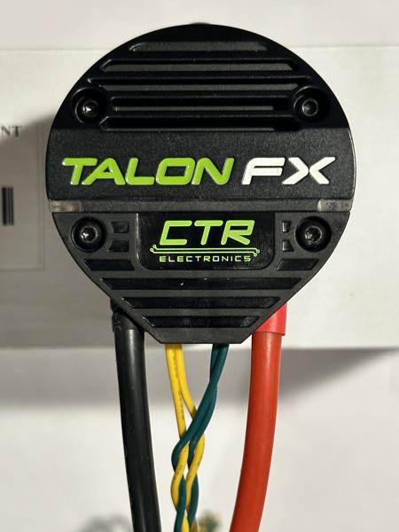
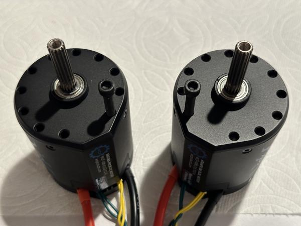
Follow these steps to assemble each motor:
- Connect the power cables (red/black) using the thick screws.
- Connect the CAN bus cables (yellow/green) using the short, thin screws.
- Install the terminal cover using the long screws.
See video (4x speed):
Note
The ring terminals should be installed with the flat side facing downward:
Note
Make sure all four connections are tight! Loose connections can be very difficult to troubleshoot later.
Note
When installing the terminal cover, make sure that the thin CAN bus cables are not pinched.
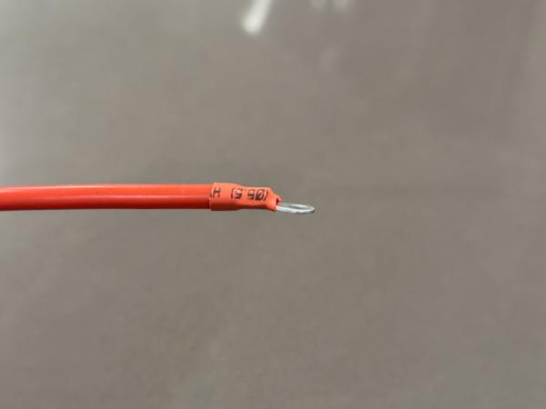
Next, use a large-gauge (10 AWG stranded) wire stripper to remove 3/8" (1 cm) of insulation from the free end of each power cable:
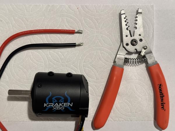
Note
Many wire strippers are designed for a maximum gauge of 12 AWG stranded (10 AWG solid), but the motor power cables are 10 AWG stranded, which is slightly larger. If using such a wire stripper, take extra care to avoid cutting the wire strands.
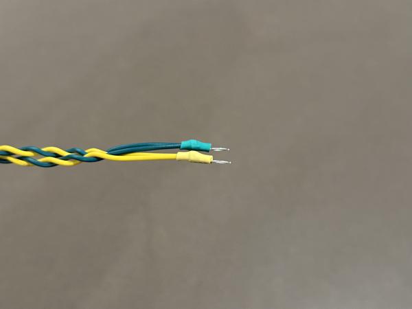
Tip
After assembling all eight motors, go through each one individually and double-check the polarity of all four wires. The wire colors should match those shown in this photo (black, yellow, green, red):
Tip
If you are building this robot for the first time, consider leaving the terminal covers off until you have verified that the robot is operational. The covers can be easily installed later.
Caster module assembly
Estimated time: 2 hours
Tools:
- Phillips screwdriver (#1)
- Imperial hex keys (3/16", 5/32", and 1/8")
- Loctite 609 retaining compound
- Loctite 243 threadlocker
- Paper towels
You should now be ready to assemble the caster modules. In the following subsections, we will follow the swerve module assembly guide to build the modules, with a few slight modifications.
Note
Screws used in the caster module should be fairly tight. Fully insert each screw and tighten slightly past the point of firm resistance. The exception is any screw that threads into a plastic part rather than metal (be very careful not to overtighten those screws).
Note
Apply Loctite 243 threadlocker (blue) to all screws that thread into metal. Do not apply threadlocker to screws that thread into plastic.
Note
For caster module assembly, use only Imperial hex keys (Bondhus yellow). Do not use any metric hex keys (Bondhus red).
Step 1: Encoder mounting
Follow these steps to mount the encoder onto the motor plate:
- Attach the encoder housing to the plate using the two shorter screws.
- Insert the encoder circuit board.
- Secure the housing cap on top with the longer screw.
See video (2x speed):
Note
The CANcoder encoder is not part of the MK4 swerve module kit.
Tip
Do not overtighten the screw for the housing cap, as this can crack the plastic.
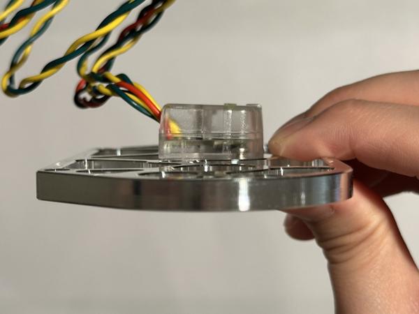
Tip
Press down on the housing cap to ensure it is fully seated. In this photo, the cap is partially seated:
Next, insert the encoder magnet into the center column and secure it using Loctite 609 retaining compound. See video (4x speed):
Tip
Loctite 609 is green, be careful not to mix it up with Loctite 243 (blue).
Tip
The retaining compound can take up to 24 hours to fully cure. If the magnet is not fixed in place by the time you run software, the encoder will produce inaccurate readings. You can check whether the magnet is secure by using a hex key to see if it can still move via magnetic force. This video (2x speed) shows a magnet that can still move because the retaining compound has not yet cured:
Step 2: Motor configurations
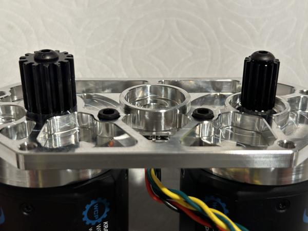
Follow these steps to secure the motors to the motor plate:
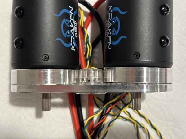
- Attach each motor to the plate using a motor riser and 7/8" screw.
- On each motor shaft, place 2 spacers (0.125" and 0.375"), followed by the appropriate pinion gear.
- Secure the pinion gears with motor screws.
See video (2x speed):
Note
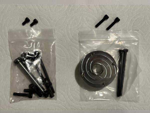
Since the Kraken motor requires risers, the longer screws included in the motor riser kit (right) should be used instead of the shorter ones from the swerve module kit (left).
Note
Make sure to use these specific screw holes on the motors:
Tip
The screws should go in smoothly without resistance. If you encounter resistance, check for misalignment between the riser and the motor plate like in the photo below:
Tip
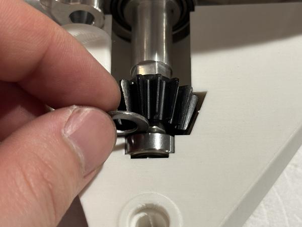
If the pinion gears are placed on the wrong shafts, the larger gear will collide with the motor plate:
Step 3: Wheel assembly
Use the three screws included with the Colson wheel kit to mount the 45T bevel gear onto the wheel hub. See video (2x speed):
Note
These screws should turn smoothly with no resistance until fully inserted. However, we have found that the bevel gear's screw hole threads sometimes have quality issues. In the video, we first insert the three screws directly into the gear to check that the threads were tapped properly.
Note
The inner face of the bevel gear should be flush against the wheel hub, and the three screws should extend slightly beyond the face:
Next, insert the R8 bearing and wheel spacer into the wheel hub on the bevel gear side, and the R6 bearing on the opposite side. See video (2x speed):
Tip
Make sure the bearings are inserted perpendicular to the housing. If a bearing becomes stuck due to misalignment like in the photo below, remove it and try again. Do not try to force it in, as this can make removal very difficult.
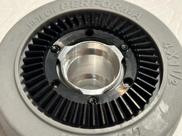
Step 4: Bearing mounting
Secure the X-contact bearing with five 0.25" screws. See video (4x speed):
Tip
There are 7 screw holes around the bearing but only 5 of them are used to mount it.
Step 5: Intermediate shaft assembly
Follow these steps to install the intermediate shaft:
- Insert a 6802 bearing into the base pulley, followed by the custom intermediate shaft.
- Install the hex bore gear onto the shaft.
- Secure the gear with the E-clip.
See video (2x speed):
Note
Our caster module uses a custom-machined intermediate shaft that is 3/8" longer than the original swerve module shaft. Here is a photo comparing the two shafts:
Tip
Make sure the bearing is inserted perpendicular to the housing. If it does not go in all the way (see photo below), remove it and try again. Do not force it in.
Tip
Check that the E-clip is fully seated in its groove, as shown in the right image.
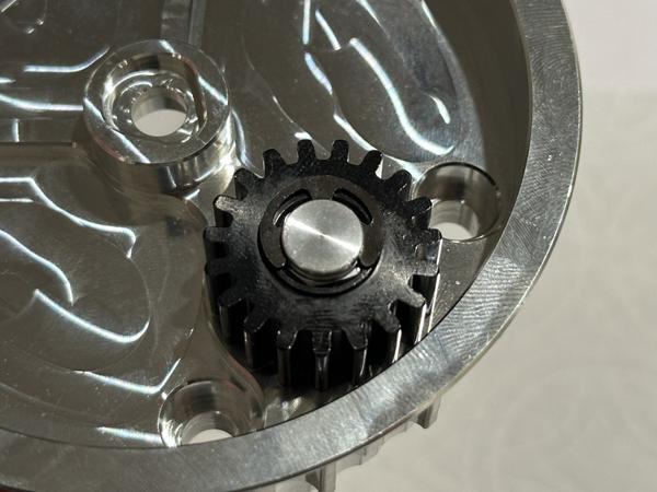
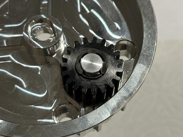
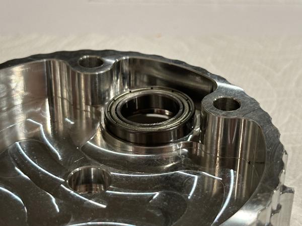
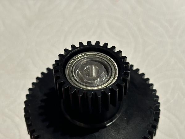
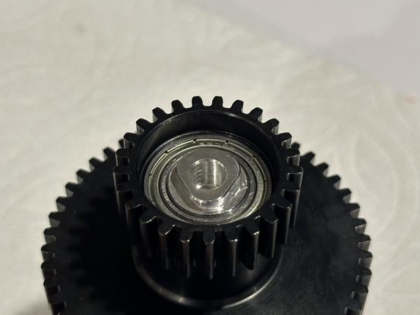
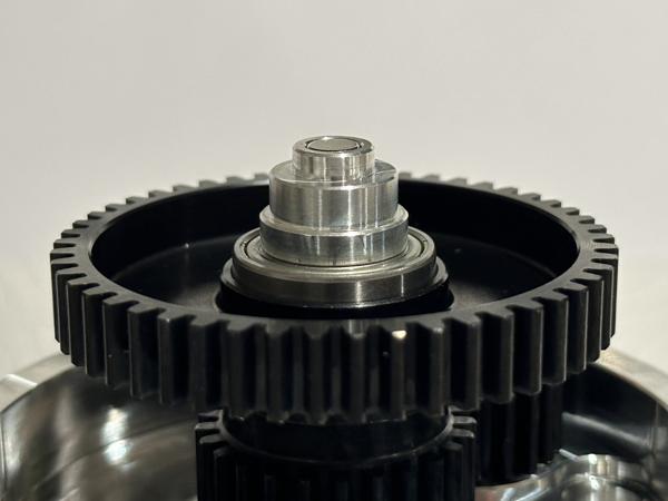
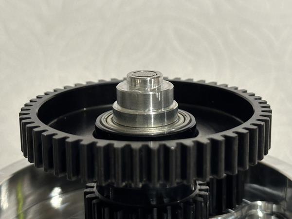
Step 6: Center column assembly
Insert two 6802 bearings into the double gear and capture with the center column and a 0.625" screw. See video (2x speed):
Note
Check that the encoder magnet is already installed inside the center column.
Tip
If a bearing does not go all the way in, it is likely due to misalignment. Remove the bearing, ensure it is perpendicular to the housing, and try again. Do not force a misaligned bearing into place.
Tip
Make sure the bottom bearing is fully inserted, with the bottom surfaces flush (as shown in the right image).
Tip
When the center column is fully inserted into the base pulley, it should be fixed in place (as shown in the right image).
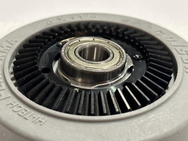
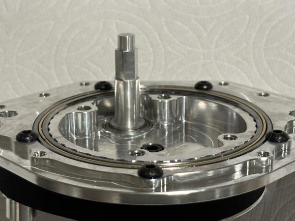
Step 7: Pulley mounting
Follow these steps to mount the base pulley:
- Install the R188 bearing into the main plate.
- Install the timing belt and steering shaft onto the base pulley.
- Mount the base pulley into the main plate.
- Fully insert the journal of the steering shaft into the R188 bearing.
See video (2x speed):
Tip
The base pulley should be properly aligned with the X-contact bearing and fully inserted. Make sure it is not partially inserted, like in this photo:
Step 8: Wheel mount prep
Follow these steps to install wheel mount B:
- Install the 688 bearing and 15T bevel gear into wheel mount B.
- Insert the intermediate shaft through the bevel gear (but not into the bearing yet).
- Place the 1mm shim underneath the bevel gear.
- Insert the intermediate shaft through the shim and into the bearing.
- Use two 0.625" screws to secure the wheel mount.
See video (2x speed):
Note
Do not overtighten the two screws going into the 3D-printed wheel mount, as this can strip the threads. If a screw suddenly becomes loose after fully inserting it, the threads have likely been stripped. If this happens, please discard the wheel mount and reprint it. To mitigate this potential issue, the 3D printing instructions for wheel mount B include reinforced walls (1.6 mm instead of the default 0.8 mm)
Note
Do not tighten the screws too quickly as the resulting force can strip the plastic threads in the screw holes.
Note
Threadlocker should not be applied to the two screws because they thread into plastic.
Note
After installation, wheel mount B should sit completely flush against the base pulley. If there is a visible gap like in the photo below, please discard the part (since the tapped holes are misaligned) and print a new one.
This issue may also result from an inaccurate print. Double-check that bed leveling was performed recently, or consider using a higher-quality 3D printer.
Note
It is very important that there is no gap between the wheel mount and the base pulley. This video demonstrates how such a gap can cause the gears on top to mesh too tightly:
When the gears are too close, they will produce loud grinding sounds. This video provides an auditory comparison between normally spaced gears and gears that are improperly spaced:
With correct spacing, the gears should spin freely, as shown in this video:
Note
The wheel mounts should not exhibit any cracking, such as shown in the photo below. If cracking occurs, double-check that the part was printed with proper support for all overhang regions.
Tip
Don't forget to include the shim underneath the 15T bevel gear:
![]()
Tip
We use the partially inserted shaft to prevent the shim from falling into the recessed area behind the gear:
Step 9: Wheel mount assembly
Use two 1" screws to install wheel mount A. See video (4x speed):
Note
Do not overtighten these screws, as it can make it difficult to insert the wheel in the next step.
Note
While we mostly follow the same steps as the official swerve module assembly guide, we reordered steps 9, 10, and 11 because our modified wheel mount A must be installed before the wheel to avoid obstructing one of the screw holes.
Tip
If you are having trouble aligning the screws, it might help to look more closely at how the wheel mounts fit into the base pulley. See video (2x speed):
Step 10: Attach wheel
Insert the wheel between the wheel mounts and secure it with the shoulder bolt. See video (2x speed):
Note
Do not overtighten the shoulder bolt as it may bring the bevel gears too close together, leading to loud grinding sounds.
Note
The wheel should spin freely once installed, as shown at the end of the video. If it does not, try adjusting the shoulder bolt tightness or using a different 3D-printed wheel mount, as slight variations can occur between prints.
Note
Threadlocker should not be applied to the shoulder bolt, as it threads into a plastic part.
Note
To avoid stripping the plastic material in the screw hole, do not tighten the bolt too quickly.
Step 11: Motor plate mounting
Follow these steps to mount the motor plate onto the rest of the assembly:
- Install the steering gear and the F689 bearing onto the steering shaft.
- Install a 6802 bearing onto the center shaft.
- Mount the motor plate onto the assembly, making sure both shafts are fully inserted.
See video (2x speed):
Next, secure the four spacers with four socket head cap screws. See video (4x speed):
Tip
The socket head cap screws used here have two different lengths: two of them are 2.5" long, the other two are 3" long.
Assembly complete
Your caster module is now fully assembled. Please repeat the process to build a total of four caster modules.
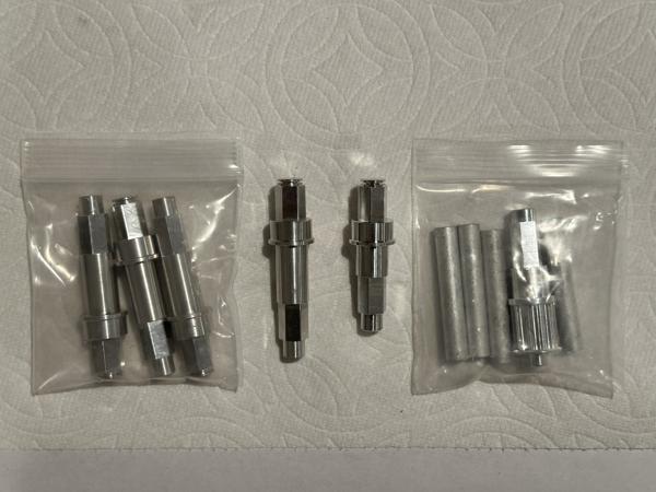
Note
The following parts should be the only ones left over after assembly:
- The two wheel mounts and the intermediate shaft are not used because of the swerve-to-caster modification.
- The four black screws are not used because the Kraken motor risers require slightly longer screws.
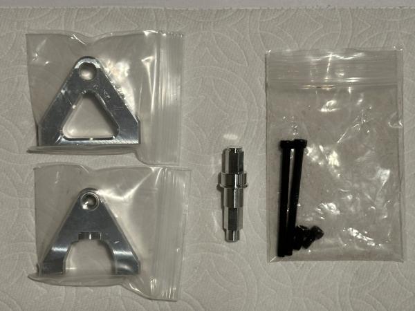
If you have other leftover parts not shown here, please double-check whether any step was missed during assembly.
Lubrication
Estimated time: 20 minutes
Tools:
- White lithium grease
- Paper towels
The gears in each caster module should be greased periodically for smooth operation and longevity. Each module contains 8 gears, make sure to apply grease to all of them. Afterwards, wipe away any excess to prevent buildup.
Here is a video (4x speed) demonstrating the lubrication process: