Power system
Estimated time: 30 minutes
This page describes how to set up the power system, which supplies power from the sealed lead acid (SLA) battery to the motors and encoders.
Power cable assembly
Tools:
- 5mm hex key
- 5/64" hex key
- Socket wrench with 10mm socket
- Electrical tape
- Zip ties
Follow these steps to assemble the power distribution panel (PDP) and power cable:
- Connect the power cable and 120A circuit breaker to the PDP.
- Use electrical tape to cover any exposed connections and secure the tape with zip ties.
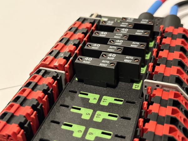
- Install the eight 40A breakers into channels 0-3 and 12-15.
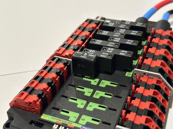
- Install the 5A breaker into channel 4 along with the terminal spacer.
See video (4x speed):
Note
Make sure that all power cable connections are tight! Loose connections can be very difficult to troubleshoot.
Note
The 40A breakers should be fully inserted with no exposed metal:
Note
The 5A breaker needs a terminal spacer because its terminals are too long (left photo). The spacer covers the exposed terminals to prevent accidental shorts (right photo).

Note
Use electrical tape to cover all exposed metal:

Tip
Double-check the polarity of the power cable connections. Red goes with plus and black goes with minus.
Tip
The FRC robot wiring guide may also be helpful.
Battery assembly
Tools:
- Socket wrench with 5/16" socket
- Adjustable wrench
- Electrical tape
- Zip ties
Follow these steps to assemble each SLA battery:
- Connect a battery cable using the screws, nuts, and washers that came with the battery.
- Use electrical tape to cover the exposed terminals and secure the tape with zip ties.
See video (4x speed):
Note
Make sure the battery cable connections are tight! Loose connections can be very difficult to troubleshoot.
Note
Here is how the cable should be oriented for the smaller battery:

Note
Use electrical tape to cover all exposed metal:

Tip
Double-check the polarity of the battery cable connections. Red goes with red and black goes with black.
Motor power
Tools:
- WAGO tool
Connect the power cables from all eight motors to the PDP. See video (4x/16x speed):
Note
In this step, we are temporarily wiring the motors and encoders for bench testing.
Note
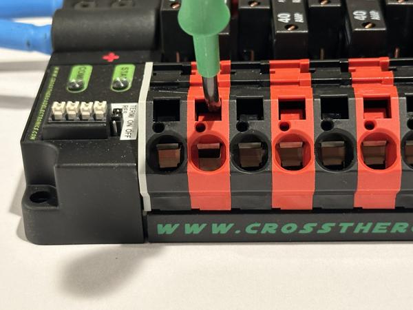
Some people may find the WAGO connectors on the PDP challenging to work with. Here is a close-up video demonstrating their usage (2x speed):
As shown in the video, the WAGO operating tool should be inserted straight into the actuation slot at a slight angle to horizontal. The end of the tool should be pushed downward to open the slot fully.
We also recommend watching this video for more information: WAGO connectors explained.
Note
Do not forcefully wiggle the WAGO tool or pry it upward! Doing so can deform the plastic housing, making the connector harder to operate in the future.
Tip
If you are having trouble getting the wires to go all the way in, look inside the wire insertion slot. Since the wires are thick, it is not sufficient for the slot to be partially open (left), it needs to be fully open (right):

Encoder power
Tools:
- WAGO tool
- Wire stripper (22 AWG solid)
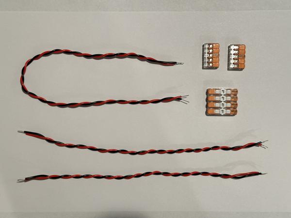
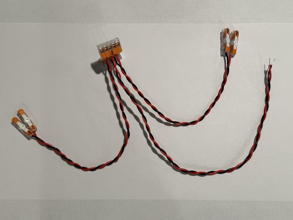
Follow these steps to build the encoder wiring harness:
- Cut three 22AWG cables: one at 45cm and two at 30cm.
- Strip 1 cm of insulation from each end.
- Use two 5-port wire connectors (one for red, one for black) to connect the wires.
- Attach inline wire connectors to the free ends of the two 30cm cables.
See photos for reference:
Note
Be sure to strip at least 1 cm of insulation. If there is not enough exposed wire, the WAGO connector may clamp onto the insulation, resulting in intermittent power to the encoder.
Next, use the wiring harness to connect all four encoders to the PDP. See video (2x speed):
Setup complete
At this point, the power system setup is finished, and you should be ready to connect the SLA battery. Make sure to double-check the polarity of all power connections (power cable, battery cable, motors, and encoders) before proceeding. Once the battery is connected, all motors and encoders should light up, indicating that they are powered on.
Note
For battery charging instructions, please see the Usage guide.